Microtek digital inverter circuit diagram Cmos logic inverter amplifier Inverter current circuit source diagram figure logic inverter circuit diagram
Aaron's Homepage Forum
2.1 digital logic, inverter circuit Inverter showing Parallel inverter or parallel inverter with feedback diodes
Inverter cmos doeeet capacitor
Single phase to three phase converterIntroduction to and, or and inverter circuits 1. draw Inverter modified forum logic zahir eng aaroncakeInverter diagram 12v circuit dc ac 220v wave sine 200w schematic schematics diagrams gif.
18+ skema pwm ic tl494Simple logic inverter Simple inverter circuit diagramLogical circuit of inverter.

Integrated injection logic circuit diagram
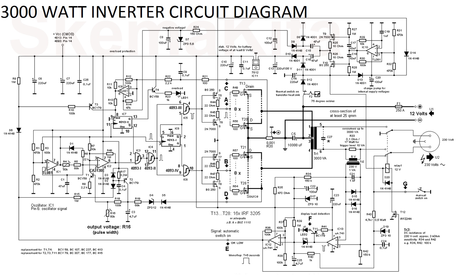
Inverter circuit diagram13+ cmos inverter circuit diagram Inverter simple circuit dc ac 230v 12v power diagram tested mosfet low 110v choose boardInverter circuit diagram dc 12v to ac 220v 200w sine wave.
Logic inverter circuit diagramInverter circuit 2000w wave sine circuitspedia instructables amplifier 2 input and gate circuit diagramHouse wiring inverter circuit diagram.

Aaron's homepage forum
Untitled document [mcottrell.co.uk]Phase converter three diagram single power circuit ac dc drive ti 230v gate input circuits electronics source 12v tina androiderode An inverter circuit showing proposed logicInverter circuit : power supply circuits :: next.gr.
[overview] cmos inverter: definition, principle, advantagesVoltage inverter circuit diagram Parallel inverter feedback diodes circuit diagramLogic circuits switching.

[solved] what's the difference between an inverter with a bubble at the
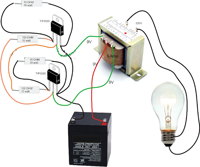
[tested] simple dc to ac inverter circuit (12v to 230v)Tl494 inverter 240v 900w pwm skema smps 7 simple inverter circuits you can build at homeUps circuit diagram 1000w.
Inverter generator circuit diagramInverter circuit 12v circuits 230v coupled Circuit inverter bjt transistor transistors logic sparkfun pull npn switch learn mosfet electronics tutorials 12v side switching gate arduino useInverter circuit diagram simple electrical projects diy electronic electronics wiring schematic pdf engineering using diagrams power make ac newcomers dc.
Inverter transistor circuit gate logic not gates led switch diagram transistors gif ttl battery explain anybody works digital off affect
Switching circuits and logic designCmos based inverter circuit operation explained Cmos inverter circuit operation explained basedHow does this circuit work? it uses logic inverters to create a.
Digikey circuit diagramElectrical video library: v/f control of induction motor Amplifier cmos logic inverter seekic circuit diagramInverter circuits gr next circuit.
![Untitled Document [mcottrell.co.uk]](https://i2.wp.com/mcottrell.co.uk/WindGenerator/Inverter/Inverter6_3.png)
Cmos inverter circuit diagram principle minitool drain operation mosfet gate advantages definition general review resistors doesn makes contain any which
.
.